
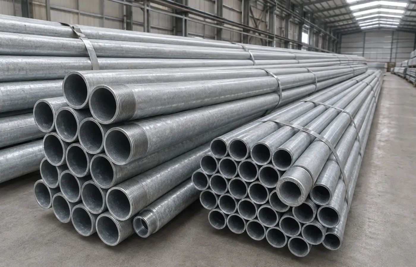
Define the service conditions first
Nominal size and length are only the beginning. Fluid, pressure, temperature, corrosive exposure, joining method and applicable rules must be assessed together. A “tested” label does not establish suitability for every service; compare the product standard, markings and test scope with the project specification.
Potable water, fire protection, compressed air, gas and process lines require different decisions. For critical systems, the designer and authorised installer must specify wall thickness, fittings, sealant, supports and testing. This guide is a workflow checklist, not a substitute for design or code.
Include thread engagement in the measurement
Do not use only the clear distance between fittings. Account for effective thread engagement, fitting centre-to-face dimensions, valves, equipment, dismantling allowance and any designed movement.
Check field measurements twice and mark the ends to be threaded. Trial-fit the first repeated piece; never compensate for a length error by bending the line or over-tightening a fitting.
Support the pipe and cut it square
Use an appropriate vice or stand, gripping firmly without crushing the wall. A wheel cutter, band saw or another approved method may be used, but the cut should be square, clean and repeatable.
An angled cut can make thread length uneven and cause a die to start off-axis. Remove sharp edges and follow the tool maker's guarding, PPE and operating instructions.
Deburr inside and outside
External deburring helps the die start correctly; internal reaming removes restrictions and loose metal that could travel through the system. Do not thin the pipe wall by uncontrolled grinding.
Reject or re-cut ends that are oval, crushed, cracked or materially damaged. Remove swarf before assembly, particularly upstream of valves, filters and regulators.
Match dies and cutting fluid to the pipe
RIDGID identifies machines capable of threading black and galvanized pipe, but the machine, die head and dies must still match material and size. Align the die and follow the prescribed feed and operating sequence.
Use the recommended threading fluid to manage heat and chip removal, and verify its suitability for the line's service. Keep hands away from rotating parts and stop the machine before inspection or cleaning.
Inspect the finished thread
Look for torn, stepped, crushed, crossed or incomplete threads. Length and taper must comply with the applicable thread system; a correct gauge and manufacturer method are more reliable than a simple trial fit.
If a fitting starts crooked, remove it and inspect. Extra sealant or wrench force cannot repair a malformed thread and may crack a fitting.
Apply a compatible thread sealant
PTFE tape, cord and compounds are not universally suitable. Confirm compatibility with pipe material, thread type, fluid, temperature and pressure, then follow the product's direction and quantity instructions.
Start fittings by hand and tighten with suitable tools and backup restraint. Avoid loading valves or equipment and do not invent a turn count or torque where the manufacturer has not specified one.
Repair coating and test safely
Cutting and threading expose local steel. The American Galvanizers Association describes accepted repair approaches including zinc-rich paint, zinc solder and thermal-sprayed zinc; select the method required by the specification and service environment.
Have authorised personnel test the system using the method, medium, pressure, duration and exclusion zone defined by design and regulation. Never tighten a live test joint; record supports, alignment, coating repair, cleanliness and test results.