
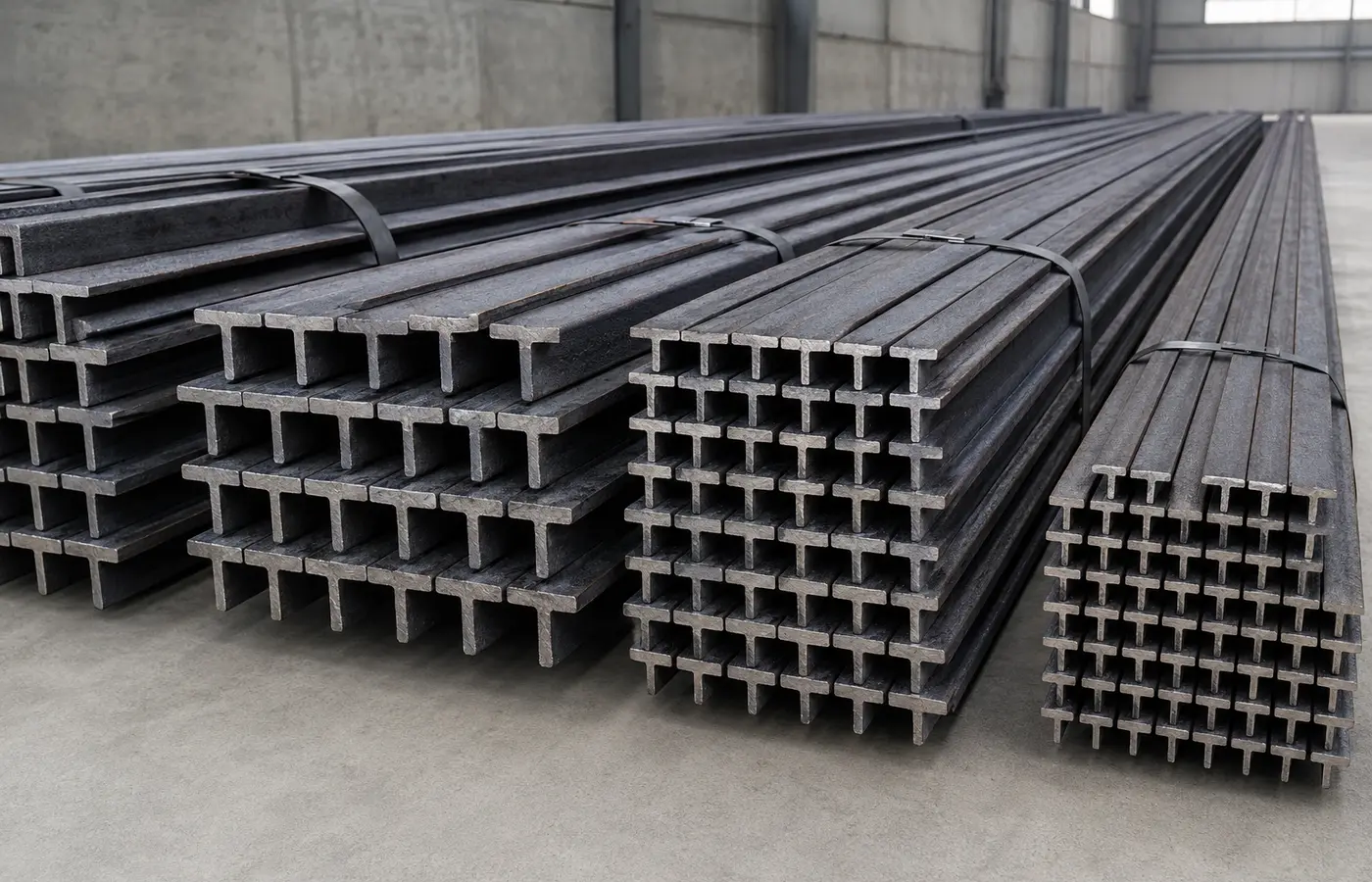
Specify more than the visible shape
State depth, flange width, web and flange thickness, radii, grade, condition and tolerances. Similar-looking T sections can differ in mass and properties.
ArcelorMittal lists dimensions, tolerances and grades separately. Keep material identity and documents linked to the job, especially for load-bearing work.
Fix orientation and datums
Define which flange face, web direction and visible surface belong to the assembly. Mark part number, orientation and one common measurement datum.
Avoid chained dimensions that accumulate error. Agree project-specific hole, fit-up and assembly tolerances before production.
Cut with stable support
Choose a suitable cold-cut method and clamp without rolling or crushing the section. Check the first piece for length, squareness and angle before locking the stop.
Remove burrs without grinding away the required geometry. Prepare weld gaps and bevels only from the approved procedure.
Drill without weakening the section
Hole diameter, spacing and edge distance come from the connection design. Random oversized holes can reduce net section and complicate access.
Clamp the work, select the correct tool and speed, deburr carefully and gauge the result. Repair misplaced holes only under an approved method.
Control fit-up in a verified fixture
Check diagonals, openings, flange planes and web directions together. Do not use welding force to pull badly cut parts into place.
TWI notes that tack number, length, spacing and sequence matter. Tacks incorporated into the weld require the same procedural control.
Balance weld size and sequence
Use the weld size and continuity shown by the design; unnecessary weld metal increases heat and shrinkage.
TWI recommends minimum specified weld volume, balanced deposition and planned back-step or skip sequences for long joints where appropriate. Recheck dimensions between stages.
Assess distortion before correction
Cooling shrinkage can cause angular change, bowing or twist. Restraint, presetting and balanced assemblies must form part of a planned procedure.
Measure the released component on a sound datum. AISC warns that some repairs can be more harmful than the deviation; obtain engineering acceptance before straightening.
Finish with coating and records
Clean spatter, sharp edges, oil and loose scale to the coating specification. Check coverage at roots, welds and cut ends.
Record dimensions, inspection equipment, nonconformities and approved repairs. Critical work needs the inspection method required by the project, not appearance alone.