
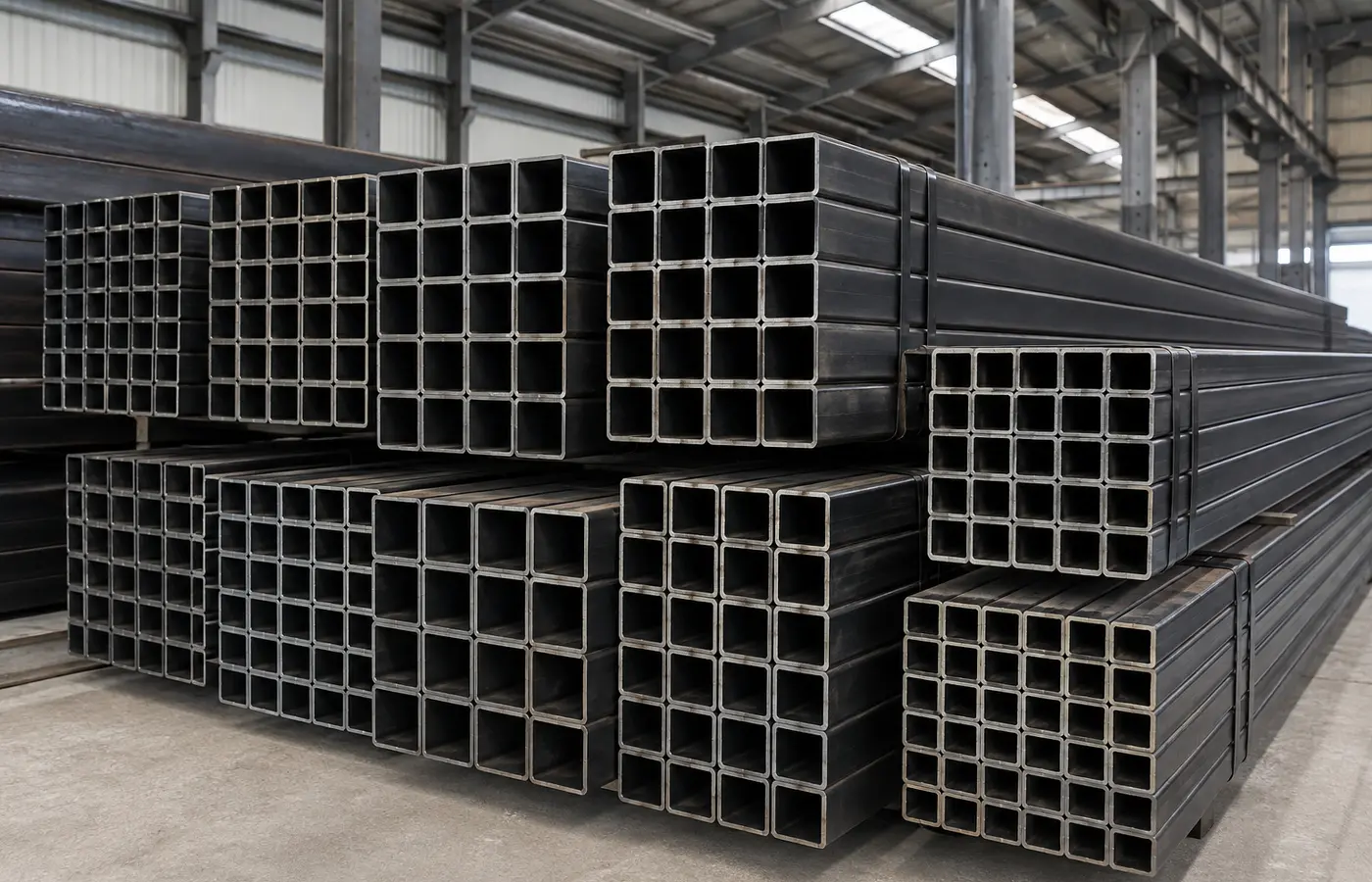
Galvanizing design starts before welding
A fabricated item is immersed in pretreatment baths, flux and molten zinc. Liquids must enter, air must escape and all solutions and excess zinc must drain during withdrawal.
Trapped moisture can flash to steam and create dangerous pressure. Poor flow can also produce bare areas, buildup and unnecessary weight.
1. Set holes from the immersion orientation
Items enter and leave the kettle at an angle. Vent at the highest point and drain at the lowest point in that real lifting orientation.
Agree hole location and size with the galvanizer for the section, volume and plant; verify structural effects with the engineer.
2. Give every enclosed cell a flow path
End plates, diaphragms and corner joints can create separate hidden cells. Each needs an inlet/drain and an air outlet.
Use open internal connections where approved and keep passages free of weld or burrs. Externally visible holes make verification safer.
3. Detail plates, stiffeners and overlaps
End plates, gussets and stiffeners can trap zinc unless corners are cropped or suitable holes are provided.
Narrow overlapping gaps may admit pretreatment liquid but not zinc. Seal, space or vent them using the applicable design standard and galvanizer review.
4. Remove residues the process cannot clean
Slag, paint, marker, grease and silicone-bearing sprays may prevent the metallurgical coating reaction.
Repair weld defects before galvanizing. Zinc does not hide seams, mill marks or grinding hollows, so establish appearance criteria early.
5. Combine steels deliberately
Chemistry, thickness and batch can change coating growth and appearance. Mixed components may finish in different shades.
Large thickness differences and asymmetric welding can increase distortion risk; consider balanced fabrication or galvanizeable modules.
6. Verify size, lifting and moving parts
Check the angled envelope against kettle dimensions. Modules joined after galvanizing may be preferable to progressive dipping.
Provide approved lifting points and allowances for threads, hinges, mating faces and zinc thickness.
7. Define inspection and repair
Inspect bare spots, deposits, sharp runs, distortion, threads and assembly faces to the specified standard—not brightness alone.
Select field repair for the permitted damaged area and document preparation, coating and environment.
Fabrication checklist
Provide:
- Section sizes, thicknesses and grades
- Overall size, mass and immersion orientation
- Vent/drain location for every cell
- End plates, diaphragms, gussets and overlaps
- Welding and residue removal
- Lift points and visible faces
- Threads, hinges and tolerances
- Standard, inspection and repair requirements